Zum Auffrischen und Schmunzeln . . .
. . . sind diese Museums-Seiten hier gedacht, denn viele wissen nicht mehr oder noch nicht, wie es damals angefangen hat und wie das wirklich funktioniert mit den Tonband- und den Magnetbandgeräten aus alter Zeit. Viele Bilder können Sie durch Anklicken vergrößern, auch dieses.
Die Magnetband zu Magnetkopf Problematik (Ampex)
Einleitung :
Eine Übersetzung dieses Artikels aus dem Jahr 1968 aus dem Englischen vom Autor.
Heutzutage (also 1968) gibt es nur Magnetbandmaschinen, bei denen das Magnetband mit direktem Kopfkontakt am Kopf vorbei gleitet. Dieser "Gleitkontakt" ist wahrscheinlich die einzige Eigenschaft, die zuletzt seit der Einführung der Magnetbandrecorder geändert wurde. Und es ist vermutlich der Bereich, der die größte Sorge der Entwickler und der Hersteller darstellt und die größte Schwierigkeit für die Benutzer von Bandmaschinen.
Grundsätzliche mechanische Überlegungen.
Wie beschreibt man diese Zusammenhänge, um sie plausibel zu analysieren und zu erklären ?
Ein Lager kann definiert werden als das Interface (der Kontak) zwischen zwei Oberflächen mit einer relativen Bewegung zueinander. "A bearing can be defined as an interface between two surfaces in relative motion." Wenn wir diese Definition eines "Lagers" so akzeptieren, dann ist der Kopf - Band Kontakt also ein Lager. Als eine schwierige Aufgabe, Verschleiß und Reibung in solchen Lagern zu reduzieren, haben sich zwei Methoden durchgesetzt.
Entweder bringt man ein leichtes (schwaches) Gleitmaterial zwischen die beiden Oberfächen, so wie etwa das Schmieröl in den Gleitlagern oder man ersetzt den Gleitkontakt durch einen rollenden Kontakt wie in einem Kugellager. Nur, keine dieser beiden Möglichkeiten funktioniert bei dem Band-Kopf Kontakt eines Magnetbandgerätes. Die Einführung eines Schmiermittels zwischen Kopf und Band wird in einer Trennnung derselben resultieren. Die daraus herrührenden Verluste können gewöhlich nicht toleriert werden, insbesondere, wenn es sich um kurze Wellenlängen (also hohe Frequenzen) handelt.
Die Funktion der Magnetbandaufnahme erfordert die relaive Bewegung zwischen dem festen magnetischen Feld im Magnetkopf (-Spalt) und dem der magnetischen Oberfläche das Bandes. Ein rollender Kontakt zwischen den beiden Oberflächen kommt so ganz bestimmt nicht in Frage. Die Kopf-Band Berührung ist deshalb ein ganz spezieller intimer Kontakt zwischen diesen beiden Oberflächen, während es gleichzeitig zwischen beiden eine konstante relative Bewegung gibt.
Um besser zu verstehen, wie dieses Interface unter diesen besonderen Gegebenheiten funktioniert, ist es hilfreich, sich die Grafik rechts anzusehen. Sie zeigt, wie die echten mechanischen Größen- Verhältnisse liegen, einerseits der extrem schmale Luftspalt (Gap) des Magnetkopfes und andererseits die Dicke der magnetischen Oxyd-Schicht und des eigentlichen Trägerbandes.
Jetzt ist es verständlich, daß (bei präziser Vergrößerung der Verhältnisse) das (Magnet-) Band keine so besonders gute Flexibilität mit sich bringt.
Nachfolgend werden die vier wesentlichen Parameter dieses Interfaces untersucht.
1. Der Band- Andruck.
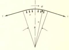
Der duchschnittlche Anpressdruck zwischen Band und Kopf wird bestimmt durch die Untersuchung des Bandes als ein freier Körper unter Vernachlässigung der Biegesteifheit des Band- Materials. Die Effekte der "Verbiegung" sind sehr klein.
Die Zeichnung auf der rechten Seite zeigt das Band als gebogenen freien Körper mit dem gesamten Biegewinkel Alpha und dem durchschnittlichen Anpressdruck (pressure) p. Der Radius der Kurve ist R und die Bandspannung (tension) ist T.
Um jetzt die Kräfte in vertikaler Richung auszubalanzieren, muß "das Integral" (die Summer der Kräfte = Gleichung rechts im Bild) der vertikalen Komponenten des Band-Andruckes auf das Band gleich sein zur vertikalen Druck-Komponente verursacht durch die Band-Spannung.
Wir kommen so zu der bekannten Erkenntnis, daß der Pressdruck zwischen Band und Kopf gleich ist der Bandspannung pro Bandbreite dividiert durch den Radius der Biegung. (Tolle Formel, das waren Spezialisten.) Weiterhin ist der Band-Andruck unabhängig von dem Umschlingungswinkel.
2. Die Oberflächen "Rauheit".
Der gerade ermittelte Anpressdruck ziwschen Kopf und Band ist der durchschnittliche Druck zwischen diesen beiden Oberflächen. Wie auch immer, wenn zwei feste Oberflächen aufeinander reiben, kann ein idealer Anpressdruck nie erreicht werden. Wegen der Rauheit (oder der Unebenheit) der Oberflächen der beiden Körper können immer nur (die hochstehenden) Teile der beiden Oberflächen miteinander in Kontakt kommen und die gesamte Druck-Last der beiden Körper wird auf diese hochstehenden "Spitzen" übertragen.
Diese hochstehenden Teile der Oberflächen werden sich jetzt so lange deformieren (oder verbiegen) bis eine genügend große Fläche erreicht ist, die den Druck auffangen (bzw. aushalten) kann. Diese resultierende (Kontakt-) Fläche ist eine Funktion sowohl aus der Geometrie der Oberflächen- Rauigkeit wie auch der Härte der Kontakmaterialien. Es ist also bei der Kopf zu Band Berührung sehr wichtig, die Oberfächen Rauigkeiten möglichst gering zu halten. Nur das hilft, die Druck- Last oder -Belastung auf eine möglichst große effektive Berührungs- Fläche der rauhen Oberfläche zu verteilen und, was eigentlich wichtiger ist, so das Abheben des Bandes vom Kopf (-Spalt) zu vermeiden.
3. Die Flüssig Schmierung zwischen Kopf und Band.
If the fluid film between the two surfaces is thick enough so that none or only a few of the asperities actually touch each other, the pressure in the fluid is given by the expression derived above. A lubricant which is almost always present between the head and the tape is the ambient air in which the taj recorder is operating. Air is not usually considered a lubricant. However, the main characteristic of any lubricant is viscosity. Air, though much less viscous than liquid lubricants, still has sufficient viscosity to act as a lubricant when the separation between the two surfaces to be lubricated is small.
Such is the case in the head-to-tape interface. The radius of the head, the speed of the tape, the tension of the tape are determined. If we assume that the transport is operating in air, then the air dragged into the interface will give a separation of:
where h is the separation in inches, T the tape tension in pounds per inch of width, the tape velocity in inches per second, a R the head radius in inches. Very few heads are actually cylindrical in shape, but in many heads a sharp corner is provided at the edges of the head. In this case the head-tape separation provided by the air film can be approximated by
where r is the (little) radius at the edge of the head, and R is the (big) average radius between the tape and the head.
Both geometries are shown in Figure on the right side.
It is obvious from the two formulas above that a small radius at the edge of the head will result in a small separation between the head and the tape.
This is the main reason that a sharp corner is provided in the so-called apex heads. Examination of the formulas also shows that head-to-tape separation increases with speed.
This the the well known increase in spacing loss encountered in tape transports at high speeds.
4. Die elastische Deformation des Bandes.
The effects examined so far have assumed that, except Surface asperities, the tape conforms exactly to the shape of the head. However, tape is initially flat and has to be de-iormed in order to conform to the curvature of the head. If a flat plate - and from an elasticity point of view, tape is a plate under tension in one direction - is bent, deformations normal to the direction of bending occur.
This, usually referred to as antielastic curvature, is shown schematically in the next Figure.
This curvature results in a bending of the tape away from the head at the edge of the tape and of a forcing of the tape into contact with the head on each side of the tape, slightly inward from the edge. This area of maximum contact pressure occurs at a distance approximately equal to 'R' from the of the tape (t is the thickness of the tape, R the head radius). For a tape thickness of 1.4 mils and a head radius of 0.3 inch, this distance is about 0.020 inch. Most of the head and tape wear will thus occur in this region, and the usually encountered head wear, near but not right at the edge of the tape, is due to this effect.
The four topics examined in detail should give the reader an understanding of some of the mechanical considerations to be taken into account in head-tape interface study. However, the effects can not usually be separated because they interact in various proportions in most heads. Thus, the entire load between the head and the tape may not be carried by the surface asperities since a certain amount of air lubrication is always present. At the same time, due to the anticlastic effects occurring at the edge, a major part of the load may be carried by the edges, so that the pressure under the tape is not exactly the one derived above.
Anmerkung des Autors mit dem Wissen von 2006
Bezüglich der Deformation oder "Verbiegung" oder "Welligkeit" der Bandkanten sei hier angemerkt, daß es bei einem 6,35mm (1/4") Band mit 2 oder 4 Spuren gerade noch akzeptabel ist, wenn sich die Bandkanten im Bereich von 0,5mm oben und unten verwerfen.
Bei den 12,6mm (1/2") Bändern unserer DLT Laufwerke mit bis zu 600 Spuren ist es überhaupt nicht mehr torlerabel, wenn sich die Bandkanten an den Rändern selbst nur 0,1mm verwerfen. Dann fehlen ganze Spur-Segmente bzw. die Daten-Blocks da drauf und die gesamten Daten sind hin.
Material Überlegungen.
It is important to understand the mechanical aspects of the head-to-tape interface so that the forces acting between the two surfaces can be determined and the effect of ambient air be ascertained. However, a major part of the interface is the interaction of the materials coming into contact. This is similar to the problem of two surfaces sliding in contact without lubricant. Unfortunately, this does not lend itself to analysis as do the mechanical aspects of the interface.
Again, this is similar to the behavior of two solid surfaces sliding in contact, where after several centuries of studies in this field, no complete understanding of two simple materials in contact has yet been obtained. Study of this interface is therefore reduced to an empirical study of the behavior of materials in contact, and the presently used heads and tapes have been designed on the basis of continuously accumulating empirical data. Such accumulation is, of course, helped by data on surfaces in contact gained in other areas where friction and wear studies have been conducted.
A program presently in progress at Ampex measures the wear rate of head materials under closely controlled environmental conditions, i.e., controlled temperature and humidity, as well as controlled operating conditions such as tape tension and speed. Data thus obtained has shown that the wear rate of most materials is: 1) a linear function of speed provided no air lubrication effect is present; 2) a function of tension and of temperature which depends on the type of tape and head material; and, 3) a very strong function of humidity. High humidity always results in high wear rates. At low humidity the wear rate may be low but, instead of abrading of the surfaces, smearing tends to occur. This results in the so-called gap smear, in which the head becomes inoperative due to shorting of the magnetic gap.
The results described apply to closely controlled laboratory conditions with presently available commercial tape. With different tapes, and if oxide is allowed to accumulate, conditions can be drastically changed. It should be remembered that iron oxide particles are very hard and therefore very abrasive. A commonly used lapping compound, known as "jeweler's rouge," is nothing but iron oxide.
Most tapes presently in use contain a lubricant within the binder. The effectiveness of this lubricant probably arises from the fact that it provides a low shear strength material between the asperities of the two surfaces in contact. Removal of this low strength material will thus occur before the asperities on the head or tape are deformed. After removal of this lubricant, the normal wear process continues until some more lubricant is exposed. This effect reduces wear but does not completely eliminate head wear and depends on some tape wear to supply lubricant.
Kontaktlose Köpfe.
Some wear will always occur when two surfaces are in contact. One way of eliminating this contact and wear is to purposely introduce lubricating air between the head and the tape. Heads, where this is done with externally pressurized air, have been fabricated and are shown schematically in this Figure.
Head-to-tape separation could also be obtained without externally supplied air by use of the effect previously described. Such separation would, however, be a function of the tape speed and tension. With an external supply, the supply pressure can be adjusted to make the separation independent of speed and tension.
With the configuration shown in this Figure, it has been possible to provide separations of as little as 5 microinches between head and tape with no measurable wear. Such separations are intolerable for extremely short wavelengths. However, with more efficient head design and higher output tapes possibly available in the future, such separations may be tolerable and still result in an acceptable signal-to-noise ratio. In other applications where the long wearing characteristics of such a head are of prime importance, such an approach may be ideally suited.
Zusammenfassung.
Head-to-tape interface present in all tape recorders is fairly well understood from a mechanical point of view. The materials problems associated with this interface are presently amenable only to empirical study, but with programs now in progress sufficient data may be available to at least predict what the effects of environmental changes will be. For some special applications where head wear is a major consideration, a non-contact head approach may be acceptable.


